This is: VR Studio
This project is Proof of Concept in the development stage.
It aims to surround listener with sphere of sounds from stereo music.
Theory
Idea for this project came up when I was choosing my project for Bachelor's degree. For that time it was too complicated to take. In mean time I've done my Bachelor's project (ANC Headphones) and Master's project (Neural Network based AEC). After finishing my studies I finally found time to work on this.
How to get sphere of sound from stereo?
First of all we need to create many of sound sources using stereo music.
To do that, we can use audio upmixer, that will provide 4, 5 or 9 sound sources. In my case I generated 9 sound sources.
This audio upmixer is an audio processing tool designed to elevate the auditory experience by transforming
standard stereo or mono audio content into immersive surround sound. These upmixers use advanced algorithms and
spatial audio techniques to create the illusion of multi-channel audio, enveloping the listener in a more expansive
sound environment.
Audio Surround Upmixers operate by analyzing the existing audio content, whether it's a stereo music track,
mono dialogue, or any other format, and then intelligently redistributing the sound to multiple speakers,
creating a surround sound effect. This redistribution is based on the upmixer's ability to identify sound elements
within the content, such as instruments, voices, and environmental sounds, and position them spatially in the audio
field. By simulating the effect of sound originating from different directions and distances,
the upmixer enhances the overall listening experience.
Upmixer diagram
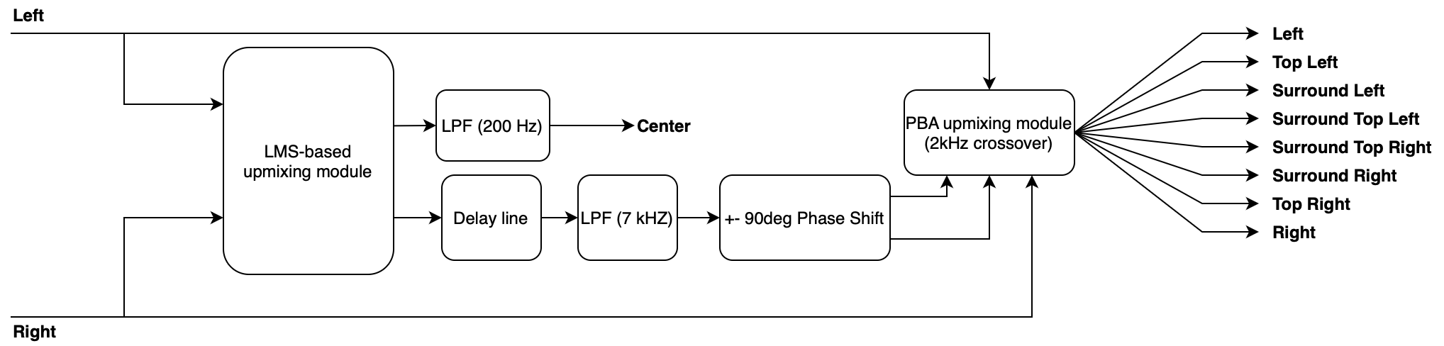
The LMS filter uses the left channel as the desired signal 𝑑𝑛 and the right channel 𝑥𝑛 as the input of a 16-tapped FIR filter (Figure 3) that provides the coefficient vector 𝑤𝑛 and outputs 𝑦𝑛 , which is a linear combination of the input signals. In the filter, filter coefficient 𝑤 𝑛 is adapted based on the error signal at the current time. The LMS-based up-mixing algorithm can be described by following three equations:
$$ {y(n)=x^T(n)w(n)=w^T(n)x(n)} $$
$$ {e(n)=d(n)-y(n)} $$
$$ {w(n+1)=w(n)+2 \mu e(n)x(n)} $$
where e(n) is the error signal that is the de-correlation part between the output of the FIR filter and the desired signal, and u is a constant step size. In the above equations, n represents the number of the current input sample, and 𝑝 is the number of filter taps. The error signal e(n) is considered as an un-correlated part that contains ambience and used for the surround channel, whereas y(n) is considered as the center channel.
It's time to simulate!
Application assumes that sound will propagate in rays. They can be reflected purely specular or with additional "noise", which comes from rougness and absorbness of material that room's walls are made of. Application has two renderers. First is based on Image Source Method. Second is based on Path Tracer. Both methods are using audio rays that are fired from every audio source and are traced for some number of reflections. If ray at any point intersects with receiver (virtual head), it is going to be processed by renderers. To get rid of doubled ray path, every path is saved into Graph. Additionally, I am using DFS to find all possible paths from source to receiver.
Image Source What?
Room impulse response simulation aims to model the reverberant properties of a space without having to perform acoustic measurements.
Image-source method is a popular and relatively straightforward geometric simulation method that models specular sound reflection paths
between the source and receiver. It assumes that sound travels in straight lines (rays) which undergo perfect reflections when they encounter
an obstacle (in our case, one of the four walls, the floor, or the ceiling of the room).
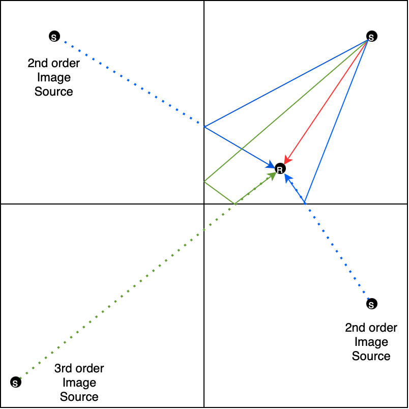
When a sound ray hits a wall, it spawns a mirrored "image" source. The image source is the symmetrical reflection of the original source
with respect to the encountered boundary. Higher-order reflections (rays that reach the receiver after bouncing off multiple obstacles) are
modeled by repeating the mirroring process with respect to each encountered obstacle.
Image source example
HRTF - How do you know if someone is behind your back?
HRTF is a fundamental concept in the realm of spatial audio and
immersive sound experiences. This phenomenon plays a crucial role in shaping how we perceive sound direction
and distance in three-dimensional space.
HRTF stands for Head-Related Transfer Function. It is a complex yet pivotal concept that describes the unique
filtering effect that our head and ears impart on sounds as they travel from their source to our eardrums.
Every individual possesses a distinct HRTF, as it is determined by the size, shape, and position of the outer
ears (pinnae), the head, and the torso. These physical features act as natural filters that influence the spectral
content and timing of sounds before they reach the eardrums.
The way HRTF works can be explained by considering that sounds arriving from different directions and distances
interact with the geometry of our head and ears in a specific manner. As sound waves approach, they are diffracted,
reflected, and occluded by various parts of the head and ears. This interaction results in unique acoustic signatures
for each direction and distance, which the brain then interprets to create a spatial auditory perception.
Understanding HRTF is crucial in the world of spatial audio and immersive experiences. Whether in virtual reality,
augmented reality, gaming, or 3D audio, accurate HRTF modeling is used to replicate realistic soundscapes.
By simulating the way sound interacts with our heads and ears, audio systems can create an illusion of sound
originating from distinct spatial points. This technology enhances our perception of depth, direction, and distance,
allowing for a more immersive and engaging auditory experience.
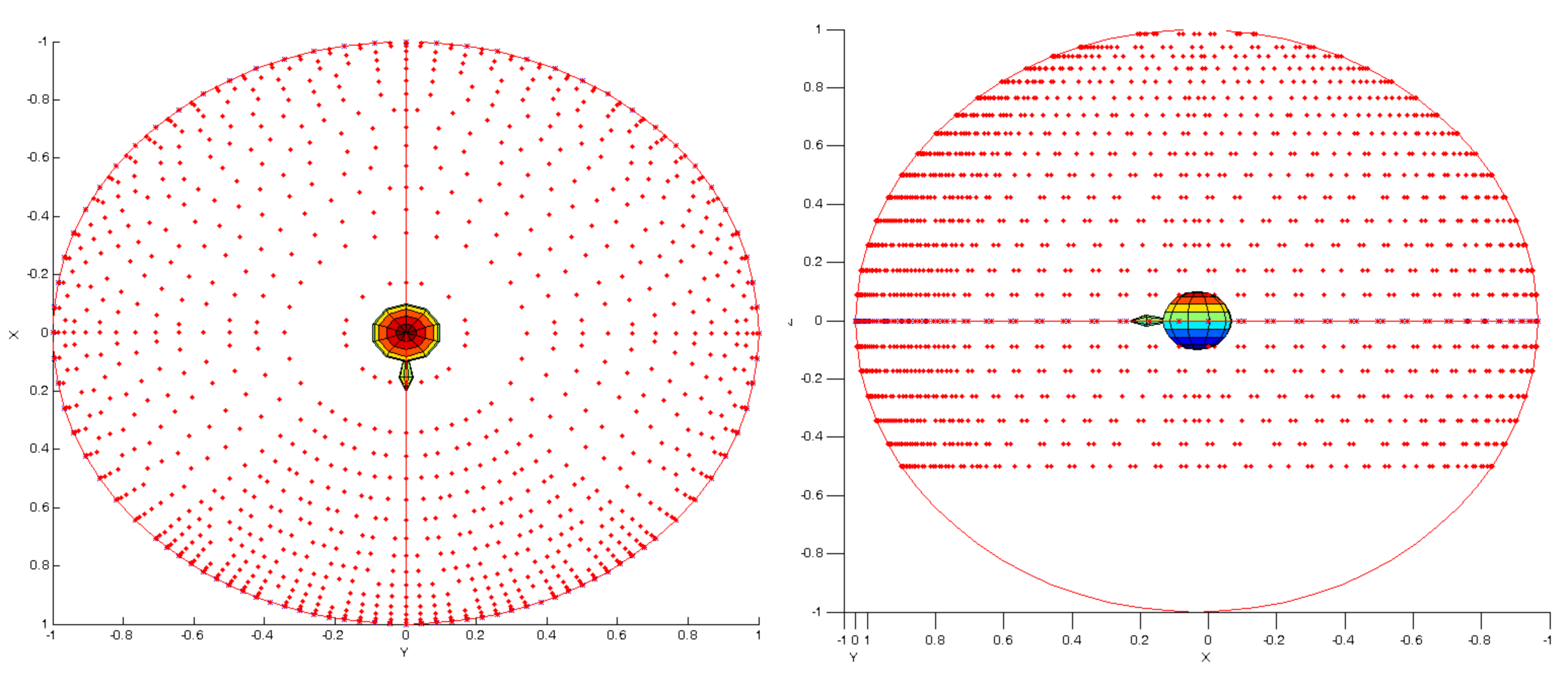
After generating proper data by both of our renderers, HRTF is used to calculate energy of ray for both left and right ear
which is later used to generate pair of RIRs (Room Impulse Response) - one for each ear.
HRTF diagram - Link to database
RIR Convolvers
A Room Impulse Response Convolver is a digital signal processing technique used in audio engineering and
acoustics to simulate the acoustic characteristics of real rooms or spaces. It is based on the concept of the
impulse response of a room, which represents how sound behaves within a specific environment. The RIR convolver,
in essence, convolves this impulse response with an audio signal, allowing for the recreation of the sound as if it
were in the modeled space.
The RIRC works by taking an audio signal, typically dry or source audio, and convolving it with the room's impulse
response. The impulse response is a recording of an extremely short, loud sound (usually a gunshot or balloon pop)
within the room. This recording captures how sound reflects, scatters, and attenuates within the space.
When the dry audio is convolved with the impulse response, the result is a processed audio signal that sounds as
though it was recorded within the modeled room.
RIR generated for path Left Speaker -> Receiver
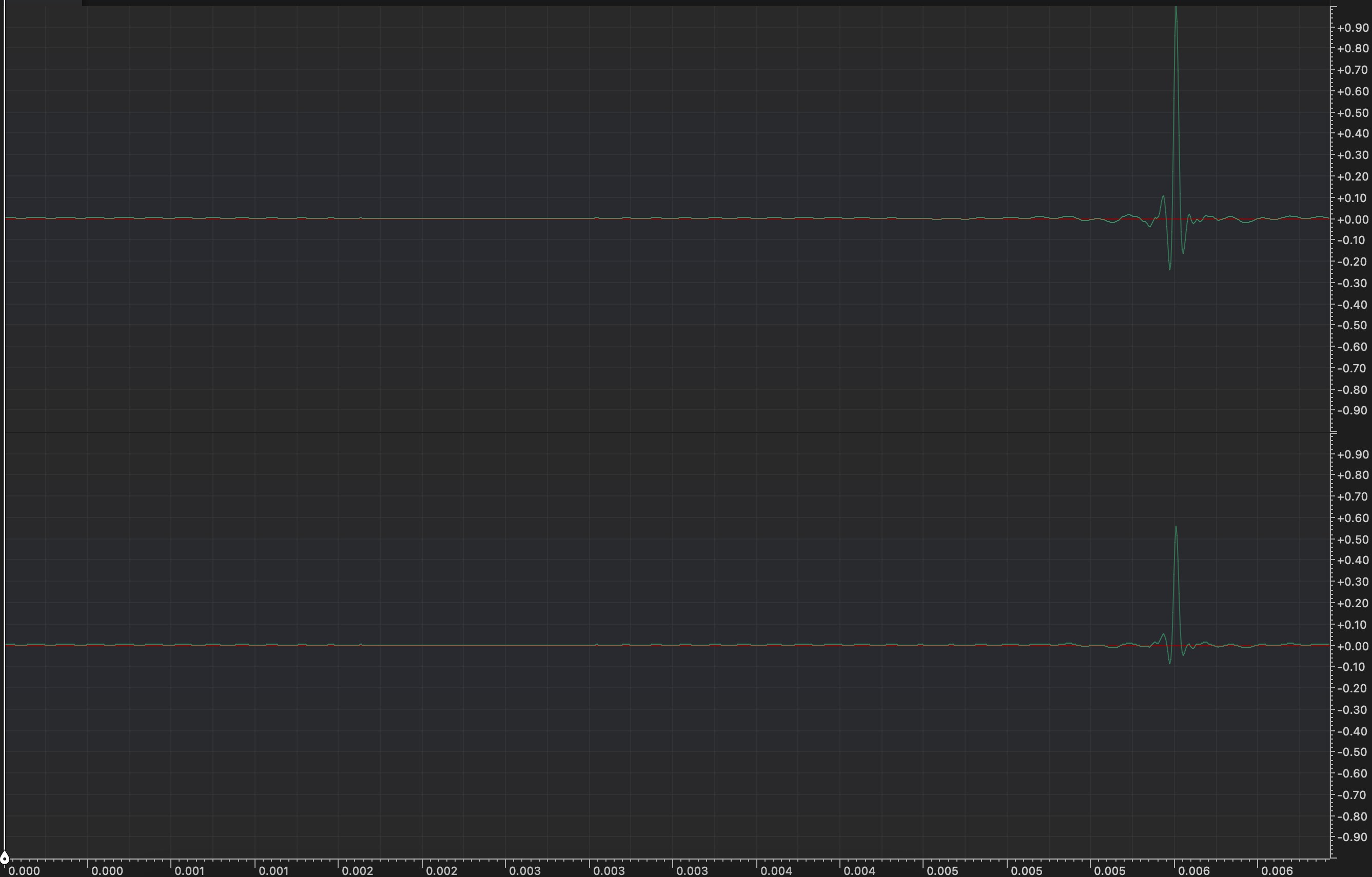
Of course left channel will be louder, since audio from left speaker will be reciver first by left ear, then right ear.
Do you want to hear it?
Put your headphones on to immerse yourself.
All files were normalized to the same perceived loudness (-12 LUFS).
You should hear main sound coming right in front of you, with additional
ambience sounds coming from behind you.
Imagine that you are sitting in the middle of quite large room (10.0m x 10.0m x 4.0m),
which is considered as "perfect" - scattering set to 0.8 and absorption to 0.9 for all walls in all band frequencies.
Now, choose your file and enjoy.